


Miscellaneous stuff
Poop deck stairs
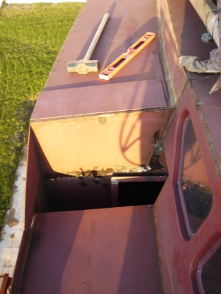
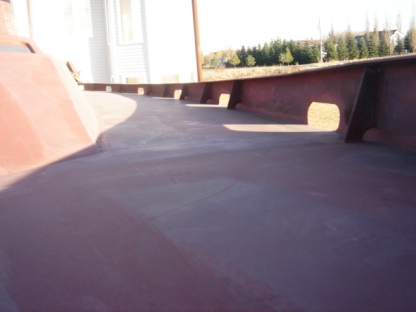
I was puzzled by the unusually high step from the deck to the poop. About 20 inches high. It could be hardly called a step, rather missing one. I decided to fix it and make a comfortable 10-inch step.
At first, you would just think that welding of two plates intersected at 90° would solve the problem. Well, this would be too easy, not to say that it would add an extra weight and create a dead space where corrosion if started, would be unnoticed. Therefore, I had to cut out the deck and the pilot house wall but not the bulkhead, which supposed to be waterproof.
Of course, after final welding was done, cutting the plates was challenging: lots of grinding along the edges. I used up the whole new 7-inch disk!
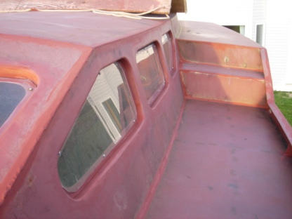
The step to the poop looks much better now. Much more comfortable to go back and forth. This will likely be a bonus in rough seas. Why wasn't it in the boat plan? :)
Bulwark
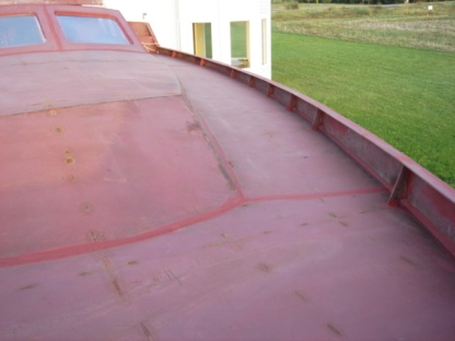
Bulwark had been on my schedule for awhile. I was debating whether to cut it curved from a plate or to bend a flatbar along the edges. Past experience with cutting flatbars with my plasma cutter showed that they rarely appear straight; therefore, chances that they would have the right curve were slim. Hence, I decided to bend a 50x5 mm flatbar. Having no bending tools, I made a genious workaround that worked perfectly.
Instead of creating lots of tension in a flatbar by trying gto curve it along the deck, I just cut it half way through where needed, about every meter or so. This cut effectively reduced the width of the flatbat and allowed it to bend easilly in that spot. Hardly noticable!
Look at an AutoCAD drawing. All deck lines are polylines, mostly composed of short length straight lines that approximate the high order polinomial curve. Therefore, in a real world every curve is just a bunch of straight lines and even CNC cutting uses them. Why bother with a bending machine?
I welded the flatbar using my favorite corner weld and backwelded it with 5cm fillet welds from underneath, spaced every 10 cm apart.
I should mention that the bulwark vertical reinforcements were part of the electronic version of the kit but did not make it to the shipped one. Hence, I had to cut them myself.
Forward jig
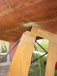
Since it is time to criticize the kit, which is still very good in my opinion, one more note about the forward jig. It overlapped the bottom welding seams; therefore, I had to trim it a bit in order to finish the welding. And after this, September 3, 2007 the final welding of the hull had been completed.
Well, the skeg/rudder, hatches, a companion way, a bowsprit and chainplates are still on the list.
Scuppers
Scuppers are better cut prior to final welding of the deck for three reasons. First, it is easier to sweep the deck of grinding dust and welding splatter. Second, it is less grinding, i.e. no need to remove the final welds of the deck to the bulwark. And third, if it rains or dews, then water will run off the deck. I had cut only one small hole on each side for that purpose. It was a bit inconvinient to dust the deck, so I used shop-vac sometimes.
Now I cut seven 5 by 20 cm scuppers on each side. Some of them may be converted to fairleads later. I smoothed the edges with a grinder. Because the radius was too small for the grinder, I even had to work with a file. I must have looked funny filing such a huge piece of steel.
Now it seems the right time to start smoothing all exterior welds in preparation for paiting next spring. I protect the ground welds with a cheap Cloverdale fast drying metal primer.
After lots of trouble with the tarp last winter due to strong winds, I'm not sure if I'm going to use it again this year. If I do, then at least I can tie it to the scuppers.
Fairing
Grinding is not an easy job for overhead welds. Overhead welding is nothing compared to the overhead grinding. This argument is often forgotten when discussing the drawbacks of an up-right hull construction. It is doable and a good exercise for certain muscles. One could stay away from a gym for a few weeks after that.
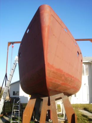
People have different opinions on underwater seams. I did grind them off flush. My thoughts behind this is are
- easy bottom cleaning
- the smoother the surface, the less marine life sticks to it
- defects in ground seams are more noticable, thus easy to detect and redo
- the seams are welded on both sides, the interior seams are left unground, hence the streangth is not compromised
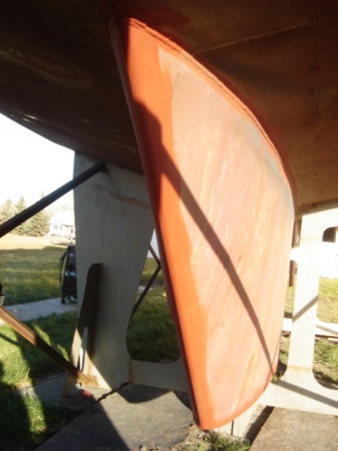
I strongly believe in metal filling rather than compound one. Therefore, I did fill all the dents, voids and scratches by welding them over. Althought it may look like a fibreglass hull on a picture or from a distance, it does not when look closely. Light creates shadows on even slightly rough surface. If you ever install drywalls in a basement, then you know what I'm talking about. Steel, of course, is much harder to sand.
I'm still to smooth out the imprints of inside welding.
Fillet welds always leave a noticable bump on the other side of a plate. People say that after sandblasting and prior to painting, it will become harder to see them but after the painting they will stand proud and will be seen from a distance. Therefore, it is essential to grind them off flush prior to sandblasting.
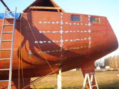
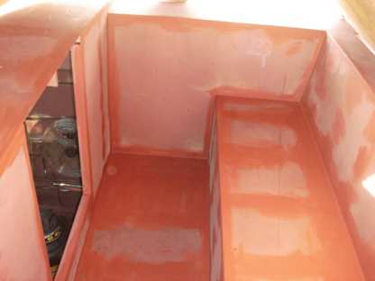
It takes time. On average, it takes two to three times longer to grind off a bump than to produce such a weld depending on a bump and how smooth I want it to be. One, of course, may translate it into total smoothing time based on the total welding time. I have already finished the deck, so for the sides and the bottom I estimate two to three weeks part time. Hopefully, there will not be too much snow by then. Bottom smoothing is hard for the hands because it involves an overhead work.
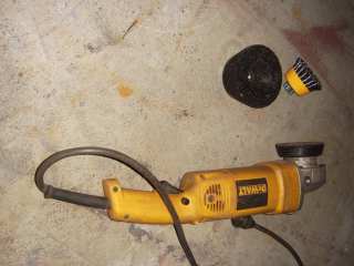
On the right is how it looks. This is about how much I can do in two hours. I use the grinding cup as oppose to a disk. See the left picture. It grinds faster and takes less effort. It also produces more even surface. It costs twice the disk but it lasts longer. Two cups may be enough to grind the entire hull.
Recently I was replacing brushes in my 7-inch grinder. I found that they were made a bit smarter than for 4.5-inch grinder. When they are worn to a certain degree, they release an electrically non-conductive pin that terminates a contact with a rotor, preventing a probable breakage of a brush holder and the rotor damage itself. This was exactly what had happened to my 4.5-inch grinder.
Companion way
The companion way was not included in the kit. This gave me plenty of time to think about it. The central cockpit on Voyager 388 is relatively small and I am seriously considering the use of car steering wheels on both sides of the companion way as oppose to a 40-inch pedestal wheel that would occupy the entire cockpit.
I couldn't invent anything better than just a central wide (64 cm) entrance. I am yet to make a sliding hatch on top of it. A door type is still undecided.