


Hull plates
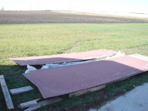
Sorting plates
It had taken six people to unload these plates, some of which were more than 200 pounds. I managed to sort them and move around alone. My poor back...
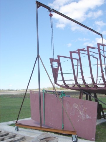
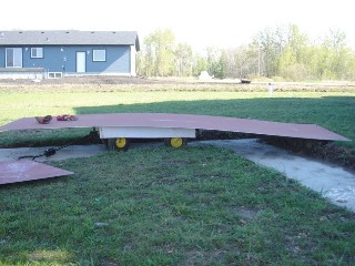
Moving plates
I used either a gantry or a garden cart to move these heavy plates around.
More often though, I stretched my muscles to load and unload these plates or to relocate them to the spot where I could reach them with the gantry.
Lifting plates
After I had prepared all six hull plates for raising, I asked Tania to give me a hand.
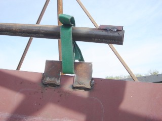
This is the simple ears, I cut using my plasma cutter from a quoter inch steel. I temporarily welded them to each of the plates when I was raising them.
The first aft plate is installed. On the picture, you can also see a 2-ton cable puller, which was very handy. I'm thinking to get another one from The Canadian Tire, since it is on sale for just $12.
The aft and the middle hull plates on the port side are done. On the starboard there is only the aft plate. Basically, it took us a day to put three plates in place. We need another day to finish them all.
Long weekend
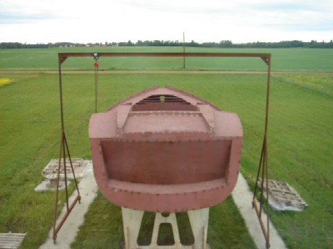
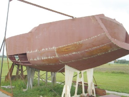
Victoria Day allowed me to finish installing the hull plates and begin the transom. Now it starts really looking like a boat!
Beautiful one! What a shape!
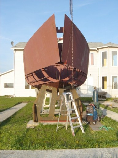
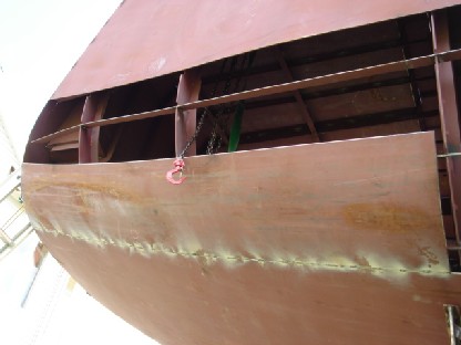
Transom
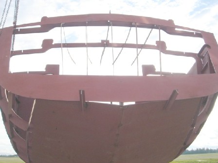
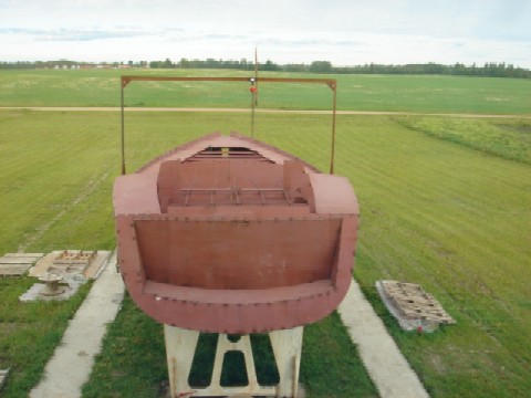
Transom as I expected is going to give me some headache. As you see on a picture, I managed to fit it in on three sides: left, right and top but the bottom is clearly out of shape.
My plan is to cut left and right bottom plates apart for about a foot from the aft. This will give them some room when I lift them up by about an inch to meet the transom.
As it happened, all I had to do was to cut the welds that were holding bottom plates and stringer at aft, then use my 2-ton hydrolic jack to shape the transom.
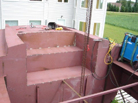
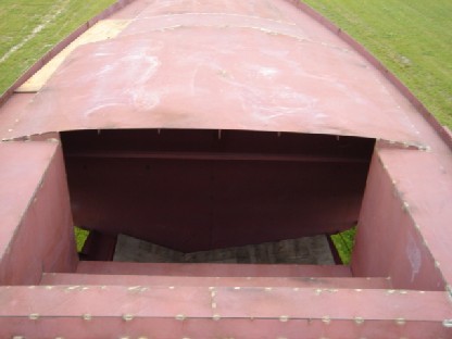
I spent entire weekend on assembling the transom. Some people prefer to do it on the ground and then install the complete transom. I decided to weld it in place, piece by piece.
This is how it looks from inside.
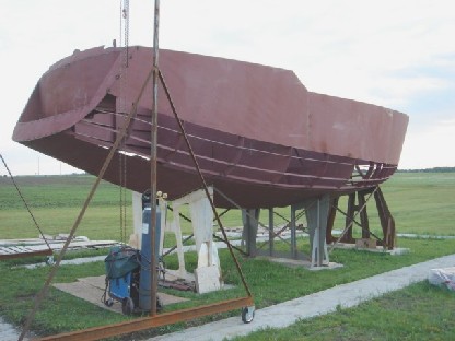
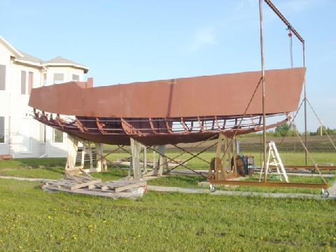
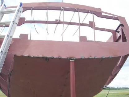
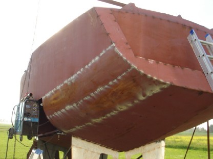
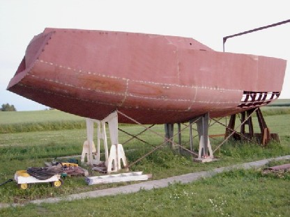
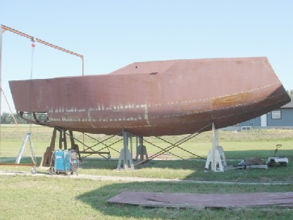
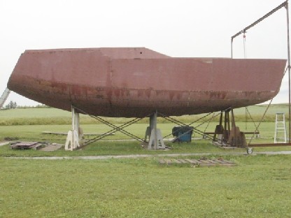
The side view of the hull with completed transom. Next - the deck - next weekend.
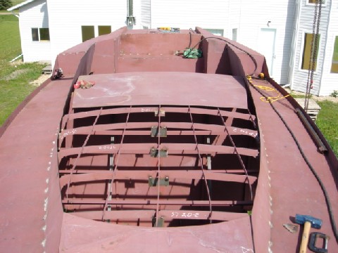
Deck
Another weekend was dedicated to the deck. It consisted of seven plates: two - aft on both sides of a cockpit, two - midship on port and starboard of a future pilot house, two long ones - from the pilot house towards the bow and the foredeck.
I started aft and moved to the foredeck as assembling instructions suggested. I had to pull and push here and there to make the plates fit the side plates' curve. But after a little struggle they all fitted perfectly, no grinding was required as it would have indicated a problem that had happened somewhere in the past and would likely have caused even more serious problem in a future.
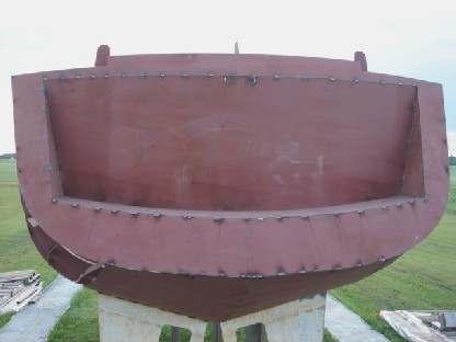
Aft deck
First and so far the only vacation day this summer was dedicated to the aft deck. Voyager 388 is designed with a central small cockpit, which looks basically like a stair way with just two stairs. I'm going to weld it next weekend and post a picture of it then, so you'll see it. Therefore, there is an aft deck and plenty of room beneath it.
Cockpit
The next weekend combined with following Monday being the second vacation day this summer was quite productive for me, mostly due to dry weather.
The previous weekend, I for the first time successfully lifted my welder to the deck, which made aft deck and cockpit welding not only possible but also convinient. Without gas cylinder it is not that heavy, only a couple of hundred pounds. I was even able to roll it over my lawn without using plywood sheets. Gasless fluxed cored wire is a definite way to go, providing a fan is used during calm weather to blow harmful fumes away.
Finishing tack weding the cockpit, I realized that Bruce Roberts had left a companion way design to a builder, which was probably the right thing to do. An unobstructed wide opening to the cabin would also allow marine diesel installation, even after a superstructure is done.
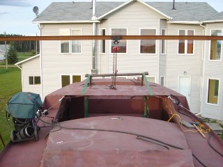
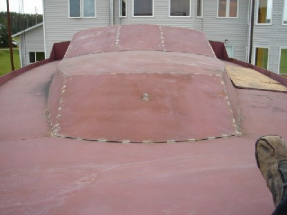
Superstructure
The next step was a superstructure. First, I welded its frames, then its side panels to the frames and to the deck, which straigtened the deck a bit and made it more rigid. Then I lifted three roof plates.

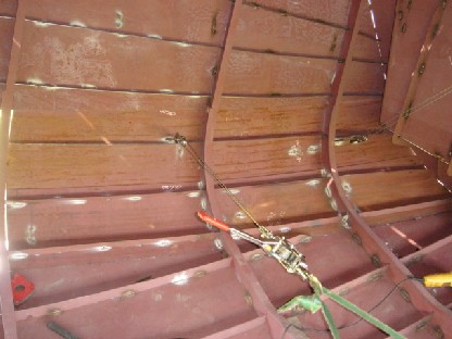
The picture to the right shows how I managed to fit one of the plates in place by lifting it with my gantry at the center, pulling down at the edges with my cable pullers and sliding the plate in between side panels.
Lastly, I welded two cabin frames, lifted up the single cabin roof plate and slightly tack welded it on both sides and underneath leaving the rest of the job for the next weekend.
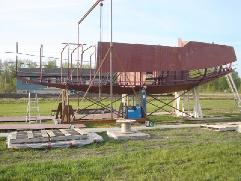
One thing that keeps worrying me is the jig. Bruce didn't provide much details about its strength. He only mentioned that it was designed to start the construction and was not meant to support a boat during the entire process without suitable reinforcement. The reinforcement details were not disclosed, of course.
Knowing that the bare boat weight, without 5-ton ballast, is 10 tons, I did reinforce the jig with flat bars at the beginning. Later on, I welded eight diagonals in between all three jigs as well. I had also seen some pictures of almost finished boats resting on the same type of jigs reinforced in a similar manner without any other supports.
Having such delusive peace of mind, I haven't noticed any signs of jig's failure so far: no cracks, bends, etc. It might just crash suddenly without any glimpse of degradation. Oops, I didn't say that, knocking on the wood...
The picture to the right is the main cabin where three windshield and three other windows on each side are going to be installed later. I'm planning to use frameless windows, which are basically the glass glued to its bed in a hull. More on this when the time comes.
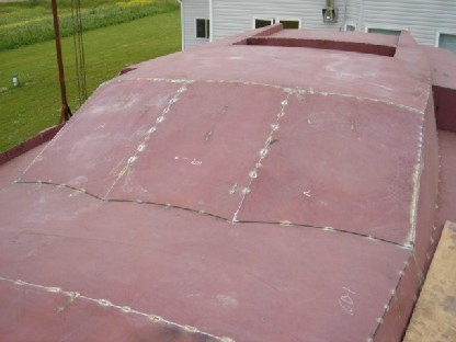
The middle plate was installed quickly and easily. To make it follow the marks, I just slightly had to lift the cabin's roof. Two other plates on both sides of the middle one, seemed to have never joined the cabin's sides. They had joined nicely along three other edges but the gap between the fourth one and the cabin's side appeared to be too wide.
Also, the confusing factor was likely incorrect, the alignment mark for these plates on the superstructure's roof. It led to about an inch ahead of a point where plates supposed to intersect. See the black highlighted line on the picture to the left. In order to follow it, I ought to either significantly raise the roof in this coner or lower it in the middle, but likely do both. Neither seemed to be possible since the roof had already been perfectly fitted around the central solid bulkhead, which was almost impossible to distort and the frame number four, which theoretically could be out of shape but I doubt it was since again, all the superstructure plates were firmly joined together without any edges being ground or cut. To make sure, I re-measured the roof height and found it correct. I'd like to say, that it's quite high - 202 cm from the floor, which means I can stand not only in the main cabin but also in the rest of the fore cabin.
I surprised myself with what a cable puller and a sledgehammer could do! The plates did join together, well, almost, just a bit more welding in the lower coner.
The complete superstructure to the left is the result of my weekend patience. I didn't count the number of times I had to go down and weld a bracket to pull plates together, then go back up to tack weld plates, and then go back down again to cut the bracket and weld it in a new stubborn spot.
To the right is where the future companionway will be. I would have to design and make it myself. There seems to be enough room for an engine installation.
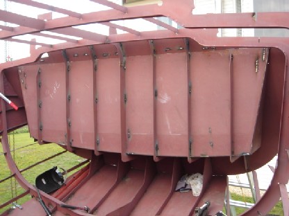
Radius plates
First radius plate is installed! I took me a day to fit it in simply because I had forgotten to leave small bridges when I was trimming its edges with a plasma cutter. Therefore, distortion occured.
The first rule of a good plasma cutter: never cut continuously, leave half an inch bridge every few inches of a cut.
Surprisingly enough, it took me another day to fit the second one in, even though I had managed to avoid the distortion this time. The plate just was slightly larger and required a lot of grinding. Here is how it happended.
All radius plates come oversized, so they must be marked and trimmed to fit. This is very smart because otherwise they wouldn't. Nothing is perfect. Oh, well...
So, I raised the second radius plate using my gantry the usual way as oppose to lifting the first one when I had to hook it inside the boat. Then I pulled it in from inside using two cable pullers. Then marked and then cut. The one thing that I hadn't taken into account was that the plate was marked being outside and therefore had to be slightly reduced to squeeze its into place.
I learned from this experience and cut the fourth radius plate couple of millimeters smaller. But I did it in a sloppy way - instead of drawing another line excactly two millimeters from the marked line, I just cut approximately two millimeters from the line.
What I saw terrified me. There was a gap on both sides, close to the end of the plate, about 8 millimeters in size! No way I could weld such a gap. I started thinking that I would probably fill it with 4-5 mm longitudinal rib.
Another remote possibility was that if I began welding from one end, more or less continuously, then the distortion might have played a positive role and paid me back for the first radius plate. I decided to leave it to my fortune or test the theory of "bad" welding.
To my total excitement, the closer I weld to the end of the plate, the smaller becomes the gap. When I had reached the end, the gap disapperared if it had never been there. The only thing that I regret is that I didn't make a picture of this gap. Who believes me besides a welder?
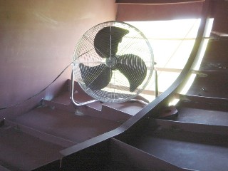
Four days of The Canada Day long weekend let me installed four radius plates. Out of twenty... Besides such a horrible ratio, there was even more horrible temperature all four days. Above thirty degrees Celsius. Imagine yourself inside a metal boat without hatches or windows for four days?! The worst sauna I had ever had. The only cure was cold showers and the big fan on the picture to the left. Still sweating...
Another weekend was not very productive mostly due to FIFA World Cup Finals and weather. Nevertherless, I managed to preliminary cut three doors. From the main cabin: one - to the forward space and two - to the aft. Doors had become a necessity for ventilation and moving around reasons. I'm going to adjust the top portion of them later when I figure out the right height for them.
Two more radius plates were installed on a port side. Only after lifting the wrong plate couple of times and blaming Bruce that they should have been marked clearly, I realized that they had indeed been marked: "P" - for port and "SB" - for starboard. Sorry, Bruce.
Another pair of radius plates is tack-welded. Now it's exatly half of them installed.
This time I did have to use an extra longitudinal stiffener to fill the gap between the radius plate and the starboard side one. The thin horizontal line in the middle on the right photo is what I am talking about.
Next couple of plates I cut really carefully, on the line. Then I lifted them again, marked the second time and ground the excess. This seemed to have worked better than trying to predict the right amount to cut, especially that cutting appeared to be less precise than grinding.
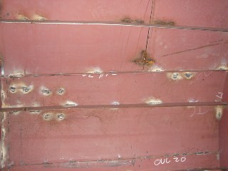
You can see the numerous welds left from the hooks that I used to pull the plates in. Later I will grind them off.
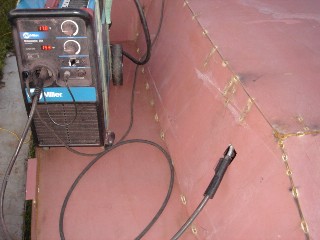
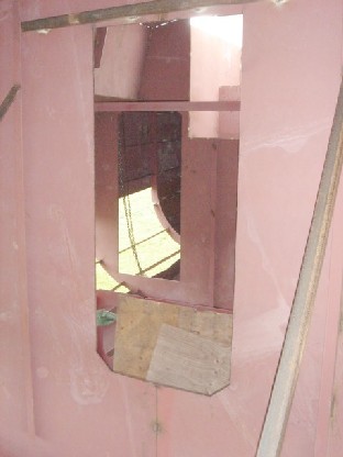
The temporary window occured to be the ideal solution to minimize the welding machine movement. After raising it on the deck, I was able to weld inside the main cabin as well as outside without moving my welder.
I cut similar one in bulwarks as well to allow rain water drain off the deck.
I decided that it was not the time to cut full-size windows yet.
Another three days of Alberta summer madness. On Saturday it was 46 degrees Celcius in the sun and 36 - in a shadow and no even light wind... Despite this hell, the record had been made: 6 radius plates in 3 days. Two plates a day!
Now only four plates left - two on each side, which is a job for another weekend or weekday evenings if I find enough time and stamina to work in such extreme weather.
Last week I got an email from Jim Farrell, Edmonton Journal reporter. I was wondering how he found this web site. I knew it was on the first places in yandex.ru search engine but not in Google. I decided to check again: search by sailboat Arcadia without quotes gave more than 50 pages and I stopped looking after that but search for "Voyager 388" gave only 14 and this web site was on the fourth page. I still doubt that Jim searched for this phrase. On the other hand, a search by "sailboat Arcadia" with quotes puts it on the first place, which is quite remarkable.
Radius plates are done! All twenty are now tack welded. She looks perfect!
The dilema is whether to begin the final welding or to install the keel first. Bruce says that the keel can be install at any time.
On one hand, I want to close all joints to prevent water from leaking inside during a rain or dew and causing rust. On another hand, keel plates are still laying on my lawn and interfere with mowing. And certainly I don't want them there for the winter.
And hey, jigs are holding so far. Knock, knock, knock. It's almost 10 tons by now.
Final welding
The long weekend in August was dedicated to the deck final welds. I managed to completely weld the entire deck just in two and a half days.
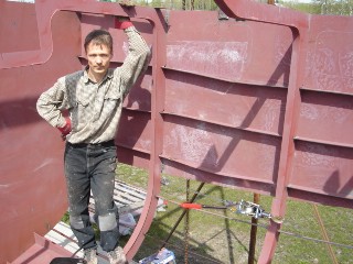
The last day I worked especially very hard trying to finish the job before dark and approaching thunderstorm. Reporters that came that morning to my surprise didn't waste much of my time. They spent about 30 minutes taking the interview and making pictures! Next day I was "a celebrity" - they dared to publish me half-naked on the first page of Edmonton Journal! After a few calls from local TV channels, I had really started regretting this publicity. On the other hand, they publsihed the URL in the paper and this allowed me to virtually meet people who were also building sailboats in Alberta prairies. Such contacts are very valuable for sharing or exchanging of boat building experience.
The downside of working very hard under my big fan all day, which was blowing away the dangerous fumes and my back, was pnemonia, which revealed itself a week later with very high fever. Now I'm still recovering for the third week and can't stand wasting such a good weather with the keel not being installed prior to winter. Hopefully, I'll be able to do it this year.
Vacation week. Still coughing but began gradually working with lots of resting.
Yesterday my 40-pound spool of E71T-11 wire suddenly ended. Today I called Arrow Welding and asked for E71T-11 0.045-inch wire. I was quoted $40 for 10-pound spool. Since I had paid about $150 for 40-pound one, I thought it's ok and drove to the store. First, I found that they didn't have that wire and second, they quoted me wrong price for E71T-GS.
I tried E71T-GS once and I found that E71T-11 is better because it's more universal. E71T-GS is used primarily for galvanized thin metal.
I decided to take two spools because I knew that E71T-11 was difficult to find in stock. Normally you have to order it.
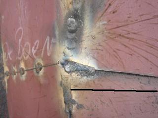
At the end of the day, I really regretted that I had bought this wire. A seam cracks when it cools down. See magnified picture of it to the left.
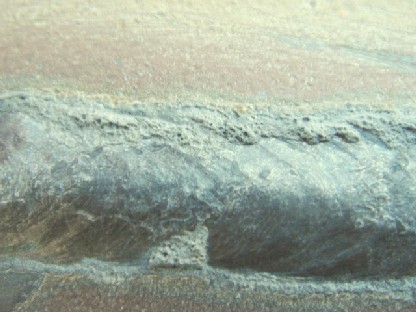
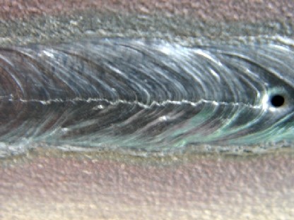
E71T-11 does not crack. See the seam produced with this wire on the right.
Today was wasted. Tomorrow I would have to find E71T-11 and redo all the welds that I did today.
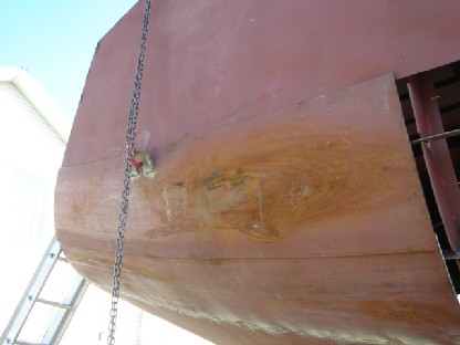
Bow cone
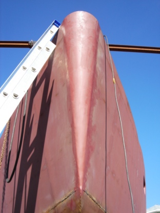
The bow cone was installed next year after I made six cabin portlites. The opening at the bow had allowed for ventilation and cooling during the final welding inside. It was very tricky to make it fit as only the very top portion was rolled to the correct radius, the rest of the cone was completely out of shape (the radius was too big; another words, it was almost flat). Even though it was oversized by about two inches on both sides, people must have had trouble rolling such a narrow piece.
I trimmed the edges and pulled it in the usual way using two comealongs from inside. Only the deck portion fitted perfectly, the rest of the cone was off by about an inch and a half. It had to be gradually pulled and hammered all the way from the top to the bottom. Also, I had to grind the stem near the bottom as it would have been impossible to make such a sharp bend there. It took me the whole day. It was very tight inside. I wish the access hole in the collision bulkhead was bigger. I should have probably enlarged it myself.