


Rudder
Balanced or unbalanced
I contacted Bruce with a question that had worried me for a long time. Voyager is designed with a full skeg unbalanced rudder, which well-known to be difficult to steer and an autopilot draws a lot of current to turn such rudder. I basically asked if it would be possbile to make this skeg rudder balanced, which is of course weird for the skeg rudder but why not. Bruce replied without any comments: "not a good idea!" This puzzled me somewhat because all the books I read say that balanced rudders are better than unbalanced because they reduce the load on the steering gear and autopilots need less power.
I can see only one advantage of unbalanced rudder compared to balanced one - its safety feature. If a helmsman finds his or her way overboard, then unbalanced rudder will be placed in a position parallel to a hull, which will most likely make a boat turn into the wind and stop.
If anybody can shed more light on this rudder matter, please email me.
Thanks Earendil who explaned the hydrodynamic difference between a balanced spade and an unbalaced skeg rudder. Skeg keeps the water flow around the unbalanced rudder less turbulent; therefore, such rudder creates more lift or turning momentum. Hence, its size can be less than the size of a balanced rudder, hence less drag. Now it makes more sense for keeping the skeg rudder unbalanced.
If I decide to use Hydrovane for my windvane self-steering system, which has an auxilary balanced rudder, then I'll be able to connect the autopilot to it.
Sacrificial skeg
Bruce designed his boats, at least in the past, with the idea of sacrificial skeg that would fall off in case of emergency. The practice showed that it rarely falls off without damaging the hull and often falls off without much of emergency.
Even though I purchased my kit less than two years ago, Voyager 388 design had still inherited this idea. The skeg is attached to the bottom plating between last two frames 9 and 10. There is no reinforcement in place between those two frames, i.e. no additional transversal or longitudinal members. Bottom plating has 6 mm thickness as everywhere else; therefore, no extra strength there either.
Without proper reinforcement, application of constantly varying forces on skeg would cause flexing in the bottom plate and its fatigue. Another words, the bottom plate will fail faster than the welding seam of a skeg to it. It is also a well-known fact that steel welds can potentially be made stronger than the base material.
Even if the skeg falls off in rough seas without causing hull damage, loosing a rudder and steering may still be fatal to a boat and a crew.
Later Bruce came up with his safety skeg design where the skeg is connected to the keel with a heavy square pipe. He offered me the modification for my Voyager 388 free of charge. It did not seem to me an attractive solution though. One of the reasons was that the pipe increases the chances of underwater collision with a floatsome or during grounding. In any case, if something was going to hit that pipe hard enough, it might result in damages to both the skeg and the keel. I also doubted that the pipe of a considerable length would hold the skeg as it was prone to deformation on its own.
There are few things that I'm planning to do to rectify the potential problem. The intention is to make skeg as strong as possible and not to worry about increasing rudder stock diameter. Another words, the rudder should solely rely on the skeg for support.
Besides existing horizontal ribs inside a skeg, I'll add vertical ones, similar to the way the keel is constructed and attached to the hull. I'll then add a collar around the skeg where it connects to the hull (gusset plate) to increase the attachment area. The collar may be made of vertical ribs and a gusset plate around them or just the gusset plate. Inside the hull, right above the skeg collar, I'll weld on its extension simulating the through-hull skeg. This extension will be reinforced by one or two bottom transversal members extending to at least the radius plates.
Rudder post, port and bearings
Rudder post should be 2.5 inch stainless 329 steel. See Choosing rudder stock material . For possible construction of a rudder port see Tides Marine rudder port and bearing type C. Unsealed solid bushing type G or H could be used in fabrication of a skeg heel bearing. Locking ring separated by a washer with a ball track may be utilized to support rudder's weight.
After exchanging a number of emails with Tides Marine, we came up with the type E at the top of the rudder tube, type G - at the bottom, which has a flange that the bottom collar could sit against and the skeg bearing (does not have a link on their web site) in the removable skeg shoe. The rudder will also be supported by another collar on top of the type E bearing.
Despite that SS 329 is stronger than 316, I went with 316L due to its availability. The strength will be provided by the skeg, not by the rudder post. I stuck to the designer's suggestion of 2-inch stock. The actual size of schedule 80 pipe is actually 2 3/8". Because Tides Marine require at least 3/4" difference between the outside diameter of the stock and the inside diameter of the rudder tube, I had to go with 3.5" sch. 40 tube that has outside diameter 4".
The skeleton first, the skin next!
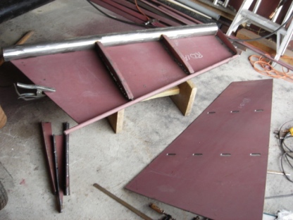
September 2007. Finally had begun skeg manufacturing - the way you should not do it. Be careful, this is not the proper way of making a skeg! It is published here to warn other people of similar mistakes. For the right way, please see the next chapter.
The skeg has only three ribs: the bottom and two intermediate. After I welded 25x4 mm flat bars to them that were going to serve as backing plates for plug welding of the skin, I welded the ribs to the port plate, shaping it along the ribs as much as it allowed me. Then I tack welded both 20mm rod as a leading edge of the skeg and 3" pipe. I planned to cut the half of it later. The whole pipe was supposed to deform less than a half pipe.
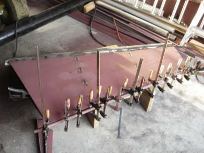
Then I turned it over and welded the starboard plate using plug welds and lots of clamps. My stitched wrist tendons got a good test with those hand-tightening clamps. The tendons withstood the abuse, my skin doesn't. The clamps were not enough though to make the forward edges meet. I also had to use vise grips and a sledgehammer combinded with the heat produced by GMAC welding.
Yes, in preparation for stainless steel welding I switched back to gas welding. Just to refresh my skills. It is different and it is hot. Splater is bigger too, not as fine as with flux-cored wire. Even though it produces less smoke than gasless welding, it is more dangerous for human health as I found from the list of hazardous materials contained in welding fumes of hard and flux-cored wires. This immediately resulted in a headache. Better do it in a welding respirator too.
I rushed finishing the skeg and welded it all up just to realize that it got terribly twisted along the vertical axis. It was hard to notice in horizontal position. It was impossible to avoid using the above fabrication technique.
I read somewhere on the internet about a rudder construction that began with the ribs welded to both pipes or rods that form the forward and aft edges. This recallection made me understand my mistake: skeleton - first, skin - next! The plate, either starboard or port or both were twisted and consequently led to the ribs being welded to the pipe and the rod at a different angle.
At first, I thought that it would be easier to make a new skeg but then found that I only have spare 5mm plate enough for cutting out just one side. Demolition is inevitable.
The right way
Demolition or "testing the welds"
Well, demolition wasn't that scary. How else would one have tested the welds quality? ;) It took only 5 hours to return to the starting point. 6 5-inch cutting disks went in no time; therefore, I had to use grinding ones and a plasma cutter. All welds were good - deep penetration, etc! I had to make the new bottom rib and cut a new rod for the forward edge. I was to re-use the pipe. I also cut vertical ribs that were to be welded to the hull bottom, the same way as for the keel. Those ribs were not part of the original design.
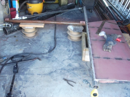
I began my new attempt with bracing the pipe in between two angles, then welded the horizontal ribs to it making sure that they are centered and vertical. Then I welded the rod on top of the ribs. This approach resulted in the perfect frame for the skeg.
Leveling the skeg
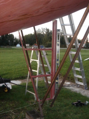
The next thing I decided to alter was the sequence of the construction steps. Instead of finishing the skeg and then welding it to the hull, I decided to weld the frame to the hull first and then put the side plates on.
I think it was the right way to do. A heavy skeg would be very difficult to align with a bottom. I spent probably an hour ensuring that the frame was welded in vertically. As my concrete pads sank slightly overtime, the hull was no longer leveled. Hence, I could not just rely on the level. I had to take measures from the bottom of the skeg to certain points on the hull and confirm that they were equaled on both sides.
The next right thing was to secure the frame for the rest of the construction, which I achieved with four heavy angles welded to the hull sides. This angles not only held the skeg and prevented it from the deforming during the welding and shaping but also helped as a fulcrum for come-alongs and a jack.
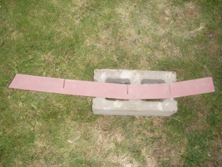
Forming the plates
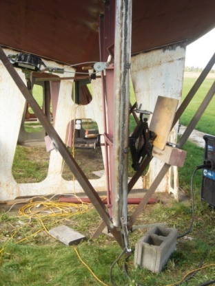
This picture illustrates how I managed to put the plates back to their shape. I should have said that after taking my twisted skeg apart, they were much more deformed than the new ones. They tended to form a cylinder, only in the direction perpendicular to the desired one. I was not certain if this had something to do with how they had been originally cut from the plate but on the cutting files, they were nested parallel to the long dimension of the plate. This would have explained the curving assuming it was the hot rolled plate.
Speaking of the skeg shape, I should say that three ribs are not enough to form 5 mm plate to a given curve. At least 5 would be necessary to avoid uneven curving. Alternatively to extra horizontal ribs, the vertical ones could be utilized along the entire skeg, the same way I used them for the top portion.
Vertical ribs
I have heard too many stories of broken rudders. I don't want my rudder to be among them. Here I adopted the keel construction technique and welded vertical ribs to the hull. Inside the hull there will be bottom transversal stiffeners to support them that will extend almost to the radius plates. These stiffeners will also be combined with a "hoop" frame built on top of the skeg as an extension of the skeg; to be precise, on top of its gusset plate to simulate the through-hull skeg.
I decided to avoid backing plates for plug welding as they tend to deform the plate especially when the space is limited. 6 mm rib's width should be enough for this purpose. These welds don't have to be very strong.
Building the skeg in place also helped with forming the forward edge that I had tough time bending with c-clamps. Now I can use the same approach that I used for the keel - make a lever using a piece of a t-bar and apply moderate force to the cable puller. Much more easier! No hand corns or broken clamps! See the picture to the left.
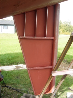
Gusset plates
To further reinforce the skeg, I used the gusset plates. I should have mentioned that I got some ideas of making a fool-proof skeg from the The Metal Boat Society forum, particularly from Brian Young. In his posting he had recommended to use a straight gusset plate as oppose to a quarter pipe. Despite that the straight plate is not as attractive as a quater pipe one, it is much stronger.
I had to play with 80x5 mm flat bar to make a good fit around the skeg. It did work on the second try. As you see, here I used the same "flat bar bending" technique that I learned when I was building the bulwark. The gusset plate increased the skeg to hull attachment area by about 4 inches making the total width of the area close to 8".
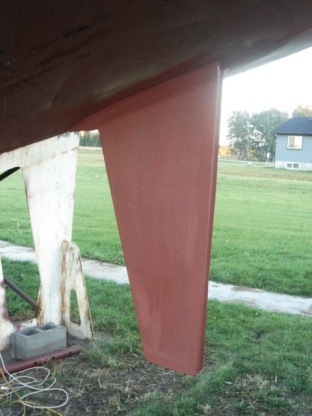
Well, almost done with the skeg. The pipe is now cut and all edges are nice and smooth. A fish scale is preserved. What left is more grinding and priming, building a removable shoe and reinforcing the skeg inside, which will be combined with the rudder tube installation. But first, while the welder is still in the garage - the rudder!
The rudder
Well, the algorithm was well-known. I was a bit scary to try my first stainless to mild steel welding on an expensive 316L 2" sch. 80 pipe. I used pure argon and 309L wire. It worked all right.
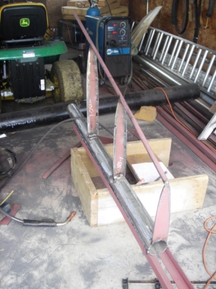
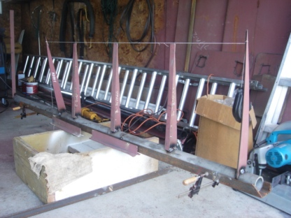
As usual, I secured the rudder stock in a horizontal position and aligned the ribs perpendicular to the stock on the same line.
After I tack welded the first plate, I realized that the stock got deformed in the plate plane. This was likely caused by welding the ribs on the same side of the pipe.
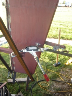
Here is how I fix the distortion. I ground off the welds between the plate and all the ribs except the bottom and the top ones. Then I used two come-alongs as shown on the picture. I need to say that I applied only a moderate force to one cable puller. When the stock was straight again, I welded the ribs back to the plate. What I realized after the final welding was that this method of straightening had twisted the stock! This resulted in the entire rudder being twisted along the vertical axis! And I didn't notice it prior to completion...
I remember that when I was checking for the pipe straightness, I saw that the label on the pipe was not parallel to my line. I thought that may be in China the labeling machine was not aligned with the pipe but how wrong was I.
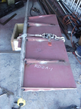
What I noticed was that any welding on one side of the rudder pipe created a distortion of the pipe. And this is the schedule 80 pipe! To the right is another picture showing the proper way of fixing the distortion caused by welding the top rib. It might have been wise to brace the end of the pipe prior to welding to avoid the distortion.
The rudder twist was not as terrible as in the case of a skeg but still noticable. I'm not sure if it qualifies re-making of the rudder. What worries me though is the ease of twisting of the 2" schedule 80 pipe! This means that under load it may twist back and forth and after a few twists it would simply break.
- Is 316L not a good stainless material for a rudder stock?
- Should I have used a solid rod instead of a pipe?
- Was it the country of origin that made a poor pipe?
I would be grateful to anyone who can shed some light on this issue.
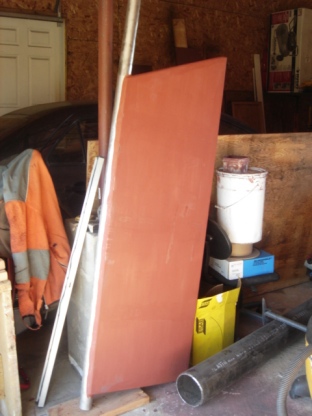
Here is the finished rudder put aside until I find the answers to the questions above. Meanwhile, I decided to work on the rudder tube and skeg reinforcement inside the hull.
I decided to do my own research in the "strength of materials" area. Wikipedia article had a link to the University of Wisconsin-Stout Physics Department Strength of Materials online course where I learned some simple math. Here are the direct links:
First, I assessed the maximum angle of the twist in my rudder. The twist was completely hidden by the rudder post, i.e. not seen if looked at it from the rudder stock side. The stock has 6 cm diameter plus 5 mm side plate thickness times two. The rudder is approximately 57 cm wide. Applying a trigonometry, I could estimate the angle of the twist to be within 6 - 7°. For simplicity sake, let's say it is π/30 rad.
To calculate the torque necessary to twist the rudder post by this angle, I used the formula
T = φ x G x J / (L x g)
where φ is an angle in rad. G is a shear modulus and is 77GPa for 316L steel. The value was obtained from Material Property Data. J is a polar moment of inertia, which is calculated for a pipe using the formula
J = (π/ 32) x (do4 - di4), where do and di are an outside and inside diameters of the pipe respectively. L is the length of the pipe. In my case, it seemed to have been the length of the rudder because it was twisted by being fixed in between the top and the bottom ribs. g = 9.8 m/s2. All calculations are in Si.
J = (3.14/32) x (1322 - 513) x 10-8 = 79 x 10-8 m4.
L = 1.5 m.
This gives
T = (3.14 x 77 x 109 x 79) / (30 x 1.5 x 9.8 x 108) = 433 kg · m.
As I used 2-ton come-along, applying less than a moderate force, it seems to be very likely that I created the above torque.
To apply the formula to the real rudder/tiller setup, the length L should be adjusted. It would be the length of the rudder post from the tiller arm to the top portion of the rudder. In my case it will be about 1 m.
To simplified the formula for my rudder stock, the torque/angle relationship can be expressed as:
T (kg · m) = 6207 x φ (rad)
Interesting to note that there is a direct correlation between the angle of the twist and the torque. For example, to twist the rudder by 1° or π/180 rad, it will take only 108 kg · m.
If I had used a solid stock as oppose to a pipe, then the only thing that would change, would be the polar moment of inertia
J = (π/32) x do4 = 129 x 10-8 m4.
It will require 1.6 times more torque to twist the solid stock by the same angle. Another words, the solid stock will resist the torsion 1.6 times better than schedule 80 pipe of the same diameter.
Skeg internal reinforcement
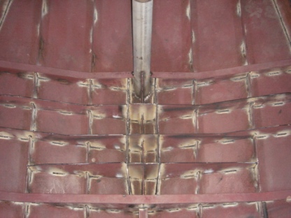
As I mentioned before, there were no transversal stiffeners between frame 9, the forward end of the skeg, and frame 10, the aft end of the skeg, where the rudder tube is located. You may identify them on the picture by the flanges. Therefore, I built what people call "a hoop frame" on top of the imprint of the skeg's gusset plates. I bridged them with three short transvesal plates positioning them above the vertical frames of the skeg and continued them for another 2 to 3 feet towards the radius plates of the hull. I interlocked them with the longitudinal members similar to other frames. In fact, the stifferners were just the scaled down version of frames 9 and 10. Hence, they had drain holes on outer side of the intersections.
The entire web looks very solid now. No way the skeg can tear off the bottom here, well, unless it is a disaster, maybe. Even then, it will likely break itself.
If I give it a kick on the lower end, it vibrates like a string for a few seconds. So the skeg bearing will move sideways for a quater or even half an inch and the rudder stock must be able to accomodate such deformations without permanent distortion.