


Portlites
"Ocean Bond" windows
I read about framless marine windows and portlites construction somewhere and then I found a BC-based company, Garibaldi Glass Industries Inc. that adopted this technique in manufacturing their marine glass products, which they called "Ocean Bond".
The concept is described in their PDF document Marine window bonding using Sikaflex. It looks simple and affordable. I compared their prices for the windows/ports glass package for my Voyager 388 with offered by Bruce ready-to-install conventional windows and ports. Their price was almost three times less. Of course, it was just the cost of glass, not the complete windows but to make the frames for the glass would only take my time and not cost me extra as I have plenty of scrap metal left.
Dimensions
My problem was with the frame dimensions. The glass thickness is only 10 mm and the hull frame thickness in the area is 100 mm. Moreover, there is a 4 mm flange welded on top of the hull frame to accept wooden strips for interior finishing. In theory, the interior could be attached to the flange itself but then the metal flange is likely to become a source of condensation and possibly the reason to interior damaging. By using the wooden strips attached to the flanges with self-drilling stainless screws and put on bedding compound, the metal flanges can be completely covered with sprayed-in foam insulation.
The glass should be recessed to the hull somewhat to protect it from scratches, etc but how much? I think for a good look and maximum visibility it should be as close as possible to the hull's skin. The Sikaflex adhesive adds about 7 mm (half the width of the bedding). I decided to make 30 mm frame. In this case the glass will be recessed by about 18 mm given 5 mm hull plate thickness. Of course, this doesn't solve the problem entirely as I would have to figure something out on interior side. The angle-shape section of the frame is going be offset in by only 34 mm. The interior portion of the frame would have to be built from wood to extend it to the finishing. I could have made 100 mm metal frame but then again besides its weight it would present condensation danger and would need to be dressed in wood anyway. For some reason, I don't trust an insulating paint too much.
Supplied 4x30 mm flat bars were all used primarilly for ceiling stringers and keel backing plates. I had a big chunk of 4 mm blasted and primed plate left though. The perimeter of a frame was slightly over a meter, so I decided to cut the flatbars myself from that plate.
Here is how I made the frames.
First, I had to make templates for cutouts as marked by Bruce port cutouts on the side plates would have been too small for the Ocean Bond windows due to the flange that goes inside the frame as oppose to outside like in most conventional designs. Somehow I failed to realize this problem when I was making flanges in winter. I had made all ten of them. Well, they were not complete flanges, just the ground oval pieces. Now they have to go to a scrap yard.
Back to AutoCAD. I found myself out of practice. It took me couple of hours to scale the drawings. Basically, I had needed to redraw a few oval-shaped portlite contours using EXPLODE, PEDIT and AREA functions (AREA - to find out the perimeter of a flatbar for a frame). First time I made a mistake and forgot to adjust the radius of arcs for the corners for scaled contours. I used the same radius for all contours and it wasn't right, of course. I realized that only after I cut steel templates but fortunately prior to damaging the hull.
I should explain why I needed a few contours. Three real size ovals (the first - for the outer edge of a flange, the second - for the inner edge, the third - for the glass) would be used to verify the finished frames and order glass. The other contours would be used to make steel templates for cutting flanges using my plasma cutter. My plasma cutter burns steel 4 to 5 mm from the edge of a guide (template).
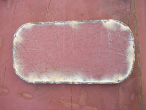
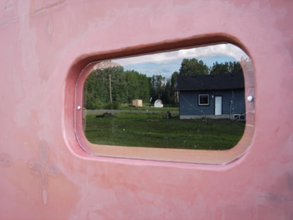
So, I fixed the paper templates, re-did steel ones and made my first cutout on the leeward side (that happened to be the starboard) to avoid rain in if it begins while I finish the portlite. What a difference it made to the cabin! Not just natural light but also fresh cooling air! It was like jumping into a pool after a hot sauna. Maybe I should have done them at an earlier stage, prior to final welding inside...
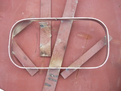
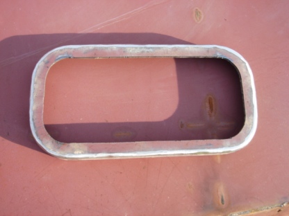
Next, I ground off the edges of the cut piece and bent my home made flat bar around it helping with the clamps and bracing corners with short pieces of a flatbar. I coudn't weld it as I went because I wanted to use a corner type weld. I like the corner weld because I can grind it off to a nice round edge. Therefore, after bracing I welded a couple of 30 mm spacers to those flatbars to keep the future flange at the right height for the corner weld. Then I completely welded it all around and only after that I cut the inner portion out to make a ring. Ground it, then the cutout, off to fit the frame and welded the frame into the cutout. Ground the edges again, made two holes to keep a temporary acrylic glass, primed, cut the glass from an acrylic sheet using scoring knife and attached the glass to the frame with two screws. The regular screws self-tapped into the drilled holes after I put some pressure on my cordless drill. The idea was that I could easily remove the glass for cooling/ventilation and quickly put it back in case of coming rain or snow. I would have to try self-drilling screws other time.
All in all it took a day (or almost 12 hours) to finish two portlites. Eight yet to go. Hopefully with some practice I can make them faster.
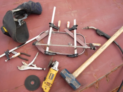
Some delays were caused by both DeWalt grinders (4.5 and 7 inches) failing at the same time. What a coincidence! I knew that the smaller one had worn brushes but I could not believe that they both wore brushes on the same day. As my poking with a multimeter showed, they didn't. The bigger one had loose crews on the wire terminals. A couple of days later I also had to clear its brushes to keep it going again but the brushes themselves were ok.
After I replaced the brushes and their ring-shape holder in the 4.5-inch grinder, it failed again right away with contact plates falling off the rotor. This was it, too many part replacements! Time to replace the whole thing. Even my trusted DeWalt didn't survive the boatbuilding abuse.
"Singlehanded" boatbuilding or black cat that crossed the road
I'm not superstitious but after a beautiful black cat graciously finishing his crossing, paused and winked at me, I thought "What on earth could happen this quiet afternoon?" But it did happen!
It began with a ladder that was blown away and made me jump from about 10 foot height at the stern. Then I was grinding the last two cabin portlites standing on a ladder, when a gust of wind was about to blow me and the ladder this time. Instinctively I tried to hold myself to the boat and released the grinder. The switch on the grinder was locked and there was no wheel guard. My hand got stuck in between the ladder and the hull and the 7-inch grinder fell on my fore arm. Luckilly, it was only 5-inch disk attached at that moment. I thought I cut the bone.
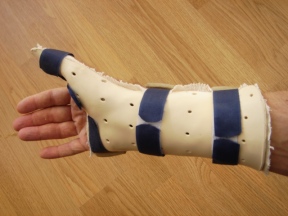
At the hospital they said that the bone was intact but at least 3 tendons was almost gone and a nerve was cut. This kind of stuff was out of competency of emergency personnel and therefore, I was referred to a plastic surgeon. He offered to attach the nerve and explore the tendons in a week. Meanwhile, the arm was stitched and splinted and in a couple of days I was back grinding the portlites, installing the bow cone and reinforcing the bulwark singlehanded. Well, almost...
While I was waiting for the surgery, I learned forearm anatomy and googled for "nerve and tendon repair". The top results give a good overview of the platic surgery state in this area:
- Peripheral nerve repair and grafting techniques: a review
- Hand, Nerve Injury Repair
- Hand, Tendon Lacerations: Extensors
Cutting a hand is not, of course, the most pleasant way to learn its anatomy but is probably the best. Ask morgue personnel.
Surgeons prefer a general anaesthetic because they don't want you to talk and bother them with your silly questions. The best way to convience the hospital to perform a surgery under a local anaesthetic is to tell them that you have nobody to drive you home. In busy hospitals that have no room for staying overnight it is likely to work. It did work in my case. Avoid speaking with a surgeon - you don't want an upgrade from the local to general, do you? Speak with anaesthesiologist instead, he has nothing to do anyway. I did and it was fun, and the surgeon was happily left alone with his gigantic microscope.
The end of the story is that I still have to wear a splint for 6 weeks and my chances for the nerve healing is about 30%. Well, at least tendons are stitched and with the type of my splint I can even work on a boat.
Remember, unless you have a black cat at home that helps you develop the necessary immunity against supernatural powers, safety is first!
On the picture above you can see the finished portlites. Acrylic glass is temporary, of course.